Wednesday, December 5, 2012

FOLDING BLIND RIVET


BLIND THREADED RIVET
FOLDING BLIND RIVET
DOME HEAD / CSK HEAD
TF SERIES


MATERIAL AVAILABLE FOR FOLDING BLIND RIVETS:
RIVET BODY MATERIAL : ALUMINUM 5052.
MANDREL MATERIAL : STEEL / ZINC PLATED.


SUITABLE APPLICATION:
·     AUTOMOBILES, MOTORCYCLES, ELECTRICAL APPLIANCES, LIGHTING FIXTURES, ETC.
·     MAKES THE GAP OF JOINING OBJECTS EXPAND FIRST THEN RIVETS THEM CLOSELY.
·     IT WILL NOT BE LOOSENED BY SHANK.
·     THE INNER AND OUTER JOINS ARE GOOD LOOKING.
·     FINISH AVAILABLE IN A MULTIPLE OF COLORS.


-OTHER SIZE, MATERIAL ARE AVAILABLE UPON REQUEST

Monday, December 3, 2012

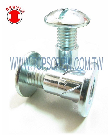
E-SELF DRIVING NUT


E-SELF DRIVING NUT

FAST & EASY!!
SECURITY!!
LABOUR SAVING!!
PERFECT OUTLOOK!!

SCREW HEAD CAN BE YOUR CHOICE!!

E-SELF DRIVING NUT features round body with fangs on it to grip the application tightly after installation with screw. TOP SCREW design this item to assist people labour saving when assembly. It is fast & easy. The most important is it cannot be disassembled easily once it has installed because security drive of screw can prevent anyone to unlock & the fangs on body would grip the application to prevent anyone who intent to pull out. The function is important but it also combines with good surface outlook, especially for customer who manufactures high class furniture. TOP SCREW also consider about satisfying visual apperance. The application can be steel, stainless steel, brass or aluminum.

Material
STEEL, STAINLESS STEEL AND BRASS

THE E SELF-DRIVING NUT OFFERS THE FOLLOWING ADVANTAGES:
  • INSTALL SLEEVE NUT TO ACCESS FRONT SIDE OF THE WORK PIECE &SCREW IN FROM BACK SIDE
  • INSTALL WITHOUT ANY COMPLICATED TOOL AT ANY LOCATION ON THE ASSEMBLY
  • INSTALL WITHOUT PRODUCING ANY HARMFUL MARK
  • INSTALL INTO VARIES MATERIAL
  • THE FANGS ON THE BODY CUT INTO THE APPLICATION DURING ASSEMBLY
  • EASY, FAST & SAFE INSTALLATION


AS THE SLEEVE NUT IS INSTALLED, THE FANGS ON THE BODY ACTUALLY CUT INTO THE APPLICATION & PROVIDES GRIP STRENGTH. WHEN SCREW ON THE OPPOSITE SIDE HAVE DRIVEN, THE FANGS WILL GRIP APPLICATION TIGHTLY. THE HEAD DRIVE OF SCREW CAN BE TAMPERPROOF OF CUSTOMER'S CHOICE.

OTHER SIZE, MATERIAL ARE AVAILABLE UPON REQUEST


HEAD DRIVE CAN BE YOUR CHOICE......


Sunday, October 28, 2012

Expansion Anchors


Expansion Anchors are typically required to join objects in concrete or masonry.  These bolts consist of a steel casing with fins at one end, and a standard screw inserted in the center of the casing.  Installers start by drilling a hole, then insert the bolt by hand.  Once the bolt is in place, a screwdriver or drill is used to tighten the screw.  This pulls the screw up inside the fins of the bolt, forcing these fins out to the sides.

Users should keep in mind that an expansion anchor is only as strong as the material in which it is installed.  This means that an expansion anchor will not hold if the surrounding surface is weak or badly damaged.  Expansion anchors may not be suitable for use in damaged or crumbling concrete or softer woods.


Wednesday, October 17, 2012

CNC Machining Part


CNC stands for computer numerical control, and refers specifically to a computer "controller" that reads code instructions and drives the machine tool, a powered mechanical device typically used to fabricate metal components by the selective removal of metal.

Our company could produce different kind of CNC PARTS by customer's requirement.

Materials used: Aluminum, Stainless Steel, Titanium, Alloy Steels, Carbon Steels & Copper


Thursday, October 4, 2012

CONNECTOR PARTS

CONNECTOR PARTS


Our organization provides various types of Connector Parts, which are available in different sizes, shapes and specifications. Moreover, these connector parts can also be customized as demands of the customers.

In electrical and mechanical trades and manufacturing, each half of a pair of mating connectors or fasteners is conventionally assigned the designation male or female. The "female" connector is generally a receptacle that receives and holds the "male" connector.
These connector parts can be installed easily and used to all kinds of parts


Sunday, August 19, 2012

SELF-CLINCHING STUDS-TSC6


SELF-CLINCHING STUDS’S HEAD SHAPE IS ROUND AND HEXAGON, BELOW THE HEAD IS A CASTLE SHAPED GROOVES.

SELF-CLINCHING ARE PRESSED INTO A HOLE IN A SHEET TO BE INSTALLED, IT WITH HIGH TORQURE-OUT AND PUSHOUT RESISTANCE, WHICH REACHED SAVE TIME AND EFFORT, SAVE SPACE, AND SAVE MONEY.

SELF-CLINCHING STUDS CAN BE WIDELY USED IN MOBILE PHONES, DIGITAL CAMERAS, MP3, DV, V8, REMOTE CONTROL, AUDIO AND ELECTRICAL SWITCHES, CONTROL PANELS AND OTHER PRODUCTS OF THE SHELL.

INSTALL SELF-CLINCHING STUDS DO NOT NEED SPECIAL DRILL HOLE.

TOP QUALITY CAN PROVIDE STEEL, STAINLESS STEEL, AND OTHER SIZE, MATERIAL ARE AVAILABLE UPON REQUEST.


Friday, August 3, 2012

GROOVED PIN


GROOVED PIN
PROOVED PINS ARE NON-THREADED PRESS FIT FASTENERS THAT COMBINE  HOLDING POWER, SHOCK RESISTANCE AND EASY TO INSTALL. PROOVED PINS ARE SOLID CYLINDRICAL PIN WITH THREE LONGITUDINCAL GROOVES, MANUFACTURED FORM BAR OR COIL STOCK. 
ADVANTAGE OF GROOVED PIN:
  • GROOVED PINS ARE SOLID
  • THERE ARE DIFFERENT GROOVE TYPES FOR A WIDE RANGE OF APPLICATIONS.
  • ONLY REQUIRE A STRAIGHT DRILLED HOLE.
  • EASY TO INSTALL AND QUICK TO ASSEMBLY.
  • REMOVABLE AND REUSABLE.


(DIMENSIONS IN INCH)


Nominal size
or Basic Pin Diameter
DABERGHIK
PIN
DIAMETER
PILOT
LENGTH
CHAMFER
LENGTH
CROWN
HEIGHT
CROWM
RADIUS
NECK
WIDTH
SHOULDER
LENGTH
NECK
RADIUS
NECK
DIAMETER
MAXMINREFMINNOMMAXMINMAXMINMAXMINREFMAXMIN
1/326     0.03120.03120.02910.015           
3/646    0.04690.04690.04540.031           
1/16     0.06250.06250.0610.0310.0050.00650.0880.068       
5/646    0.07810.07810.07660.0310.0050.00870.1040.084       
3/32     0.09380.09380.09230.0310.0050.00910.1350.1150.0380.0280.0410.0310.0160.0670.057
7/646      0.10940.10940.10740.0310.0050.0110.1500.1300.0380.0280.0410.0310.0160.0820.027
1/8      0.12500.1250.1230.0310.0050.0130.1660.1460.0690.0590.0410.0310.0310.0880.078
5/32    0.15630.15630.15430.0620.0050.0170.1980.1780.0690.0590.0570.0470.0310.1090.099
3/16    0.18750.18750.18550.0620.0160.0180.260.240.0690.0590.0570.0470.0310.130.12
7/32    0.21880.21880.21680.0620.0160.0220.2910.2710.1010.0910.0720.0620.0470.1510.141
1/4     0.25000.250.2480.0620.0160.0260.3220.3020.1010.0910.0720.0620.0470.1720.162
5/16   0.3125.0.31250.31050.0940.0310.0340.3850.3650.1320.1220.1040.0940.0620.2140.204
3/58   0.37500.3750.3730.0940.0310.0390.4790.4590.1320.1220.1350.1250.0620.2550.245
7/16   0.43750.43750.43550.0940.0310.0470.5410.5210.1950.1850.1350.1250.0940.2980.288
1/2    0.50000.50.4980.0940.0310.0520.6350.6150.1950.1850.1350.1250.0940.3170.307
GROOVED PINS DIMENSIONS
GROOVE
LENGTH
NOMINAL SIZRE
1/323/641/165/643/327/641/85/323/167/321/45/163/87/161/2
DX EXPANDED PIN DIAMETER
+-0.0015+-0.002+-0.0025+-0.03
0.1250.0350.0510.0680.0840.1010.1170.134        
0.1880.0350.0510.0680.0840.1010.1170.1340.1660.198      
0.250.0350.0510.0680.0840.1010.1170.1340.1660.1980.230.263    
0.3120.0350.0510.0680.0840.1010.1170.1340.1660.1980.230.2630.329   
0.3750.0350.0510.0680.0840.1010.1170.1340.1660.1980.230.2630.3290.394  
0.4380.0350.0510.0680.0840.1010.1170.1340.1660.1980.230.2630.3290.3940.459 
0.50.0350.0510.0680.0840.1010.1170.1340.1660.1980.230.2630.3290.3940.4590.525
0.562 0.0510.0680.0840.1010.1170.1340.1660.1980.230.2630.3290.3940.4590.525
0.625 0.0510.0680.0840.1010.1170.1340.1660.1980.230.2630.3290.3940.4590.525
0.75  0.0670.0830.10.1160.1340.1660.1980.230.2630.3290.3940.4590.525
0.875  0.0670.0830.10.1160.1330.1650.1980.230.2630.3290.3940.4590.525
1  0.0670.0830.10.1160.1330.1650.1980.230.2630.3290.3940.4590.525
1.125    0.10.1160.1320.1640.1970.230.2630.3290.3940.4590.525
1.25    0.10.1160.1320.1640.1970.230.2630.3290.3940.4590.525
1.375      0.1320.1640.1970.2290.2620.3290.3940.4590.525
1.5      0.1320.1640.1970.2290.2620.3290.3940.4590.525
1.625       0.1630.1970.2290.2620.3280.3930.4590.525
1.75       0.1630.1970.2290.2620.3280.3930.4590.525
1.875       0.1630.1960.2290.2620.3280.3930.4580.525
2       0.1630.1960.2290.2620.3280.3930.4580.525
2.125        0.1960.2290.2620.3280.3930.4580.524
2.25        0.1960.2290.2620.3280.3930.4580.524
2.5         0.2280.2610.3270.3930.4580.524
2.75         0.2280.2610.3270.3930.4580.524
3         0.2270.260.3270.3920.4570.523
3.25          0.260.3260.3920.4570.523
3.5           0.3260.3910.4560.522
3.75            0.3910.4560.522
4            0.390.4550.521
4.25            0.390.4550.521
4.5             0.4540.52
seed
note 1
22 2 2         
THERE HAS THREE HALF-LENGTH GROOVES AND SUITABLE FOR USE IN BOTH BLIND AND THROUGH HOLES AS A SPRING ANCHOE PIN.
INSTALLATOION METHOD:
   DRILLED AND DEAMED HOLE
PRESS OR DRIVE INTO PLACE
   
   LOCK SECURELY AND EASY TO SEPARATE.